
Table of Contents
- step-down transformers and their function in a control circuit.
- the importance of electrical ratings
- how to protect the step-down transformer
- typical relay in a control circuit.
- diagrams to illustrate basic electrical circuits to help you understand it.
- Finally, lots of related and resource links for in-depth related topics
Control Circuits for HVAC Systems
Control Circuits for Air Conditioning and Heating - Have you ever wondered what happens when you turn on your thermostat? All the sequences and things in the system need to work electrically and mechanically to make the system work properly. It all begins with the controls to make it work properly. Furthermore, in a basic HVAC control circuit, transformers are used to step down the voltage from the line voltage to 24 volts.

How It All Works - Transformers
Control Circuits for HVAC Systems
Step-down transformers are used for air conditioning and heating systems to step down the voltage from a line voltage to a safer and more efficient voltage for use in the control of the system. Transformers (step-down) can be 120V to 24V, 240V to 24V, and many other combinations. Some control transformers are multi-tap transformers that can be used on either 120V or 240V to step down the voltage to 24 volts. Control transformers always come with a VA rating and that gives the maximum rating for which the maximum number of loads can be used for that transformer.
Each relay or load in the control system has a VA rating. The sum of these VA ratings for all the loads in the circuit cannot exceed the VA rating on the transformer. If the VA rating on the transformer is exceeded by the number of loads in the system then the control circuit will not work properly and the transformer will fail. Additionally, it is important that an inline fuse is placed on the hot leg or 24V hot side of the transformer. Furthermore, in case there is a dead short in the control circuit the fuse will prevent the transformer from blowing.

Relays and Contactors
Relays and contactors are used in HVAC control circuits to turn things on and off such as a blower motor, condenser fan motor, or compressor. Furthermore, contactors and relays work in much the same way in a typical HVAC control circuit. They are both normally controlled by 24 volts and they typically pass line voltage to a motor or compressor. Relays and contactors have a few very important ratings on them. One is the voltage that controls the coil on the relay or contactor and the other is the amp rating of the contacts.
A relay or contactor with a 24-volt coil will blow out if 120 volts is used on the coil. The same with the contacts in the relay. If a relay with a 5 amp rating for the contacts is used to control a motor with a 10 amp rating then the contacts will burn out and the relay or contactor will be useless. If a relay or contactor needs to be replaced it needs to be replaced with an exact match relay or contactor.
Control Circuits for Air Conditioning and Heating - How It All Works
The relay or contactor is nothing more than a switch that turns on a motor or compressor. It works through the 24-volt control circuit. Some relays are controlled by other relays depending on the components in the system and the sequence of operation.

The Basic Circuit
Control Circuits for HVAC Systems
The relay in the above control diagram controls a blower motor as shown. Furthermore, this particular relay is controlled by the thermostat. The 24-volt neutral leg will run from the transformer. Then go to one side of a coil on the relay. The 24 hot leg of the transformer will go through the thermostat. And then to the other side of the relay coil. When the switch in the thermostat closes it completes the circuit. Lastly, this energizes the coil closing the contacts and turning on the blower motor.
The thermostat controls the circuit for the blower fan. Whether the system is in air conditioning mode or if the manual switch for the fan is turned to the on position. If you have a gas furnace or other type of heating system the fan will be controlled differently either by time delay or temperature.
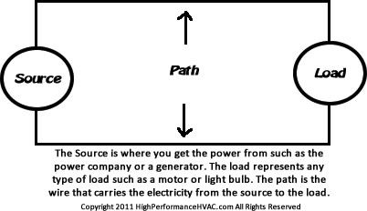
In the above control drawing is a basic electric circuit. Firstly, the source is the source of power or electricity. Secondly, the path is the wires coming from the source going to the load. Thirdly, the load is a light or a motor or something that will consume that power or electricity. It works the same as described above. Furthermore, the transformer is the source, the wires being the path, and the coil in the relay is the load.
Related posts to help further your knowledge. Learn the basics of electrical circuits include Ohms Law and HVAC and articles found here at High Performance HVAC.
 Control Circuits for HVAC Systems
Technical Resource: Refrigeration and Air Conditioning Technology
COVID 19 Home Protection
UVC Light to Kill Viruses and Other Airborne Harmful Things that Affect Health
For additional protection, you can also use UV Light that will kill harmful viruses and bacteria inside the airflow of the air handler. In labs, researchers used a spectrum of ultraviolet light called UVC to kill viruses. This product requires professional installation so it will turn on and off with the blower fan in your air handler but it will offer the protection you need for you and your family from any viruses.
Click the image to the right for purchase options of the UV light to protect your family.


your site was very helpful , thank-you
your wvaryebsite was very helpfull , thank-you
I need to find specific instructions (step by step)in how circuit boards control the operation of the components in HVAC systems today. I am very familiar with the operation of relays and contactors in older models, and I need to get up-to-date with the new circuit boards operation and troubleshooting, so I can share with my team members. If possible, share specific step-by-step instructions please. Thank you very ,much!!
this all depends on the product and what the design sequence of operation is for that particular equipment. Unless it is the same model number and year every piece of equipment is different for control. Additionally, commercial systems are typically retrofitted with additional control systems. If you have contact with the manufacturer of the equipment then it’s easy enough to simply ask them for the sequence of operation which the control board typically controls.
I was hoping to find out how relays with integral transformers work, so maybe you can answer this for me as well. A Honeywell R841C1169 for example has two leads that go to a thermostat providing both 24VAC for powering the thermostat as well as being the control wires. How is it when these are shorted the dry contacts on the primary side close? Doesn’t the fact that the thermostat is receiving 24VAC via the hot leg and returning it via the common leg all the time imply that the coil should be activated and the dry contacts on the primary side closed?
Thanks in advance.
I would have to look at the schematic to see how it works. I’m thinking it is like a relay in a box. Your 24-volt hot leg will run through the switch on the thermostat and you would likely only use the common for the relay coil. The only reason you would need to run the common from the transformer to the thermostat would be to power the thermostat if it needed power like a digital thermostat would. I looked up this type of relay and did not find a schematic for it so I could be wrong about this. So I hope this helped. If not email me the schematic. richard at (this websites name) and I will take a look and let you know.
Do you have an article about how a gas fired Furnace (and its fan) and a Heat Pump(used only for cooling) might be wired together. Please assume the reader has understanding about sources, loads, switches, relays, contactors, transformers and etc.
I think that would make a great article. Thanks for the suggestion. Just some thoughts off the top. This is called dual fuel when you use the heat pump for heat and the gas furnace for secondary heat although it will be controlled differently because it uses the gas furnace as secondary or auxiliary heat only. If you don’t want to use the heat pump in the winter then the “W” wire from the thermostat would go to the “W” terminal in the gas furnace and it is a simple matter of switching the thermostat from heat to cool when you need cooling and cool to heat when you need heating observing the provisos below.
An outdoor thermostat needs to be used to break the “Y” terminal (which originates at the thermostat, runs through the air handler, and terminates at the condenser). This will prevent the condenser from running when the thermostat is turned to heat mode. Likewise, I would also run the “G” through the outdoor thermostat to also break that (at a specific temperature) because you do not want the fan to be controlled by the thermostat in heating mode. Set the outdoor thermostat to say 60 degrees Fahrenheit and remember you would not get cooling below that temperature.
The fan in a gas furnace is controlled by a control board or by a fan limit relay that will delay the fan to turn on and turn off. You want the delay on start to allow the heat exchanger to heat up and a delay when the thermostat satisfies to dissipate heat in the exchanger. All that is controlled by the furnace.
The blower fan (in the furnace) is the same fan you are using for the heat pump in cooling mode (assuming you are using the gas furnace and have a cased coil for the evaporator for the heat pump) I digress, anyhow the fan is controlled by the “G” terminal in the thermostat and is terminated in the air handler. This turns the blower fan on and off. There are blowers in variable speed systems that are controlled by a control board in the furnace but it relies on the “G” to close in the thermostat.
The only caveat or warning would be if the thermostat has an auto for heating and cooling. In that case I would advise against using the auto feature as it would be possible for you to run the condenser and the gas furnace at the same time. In other words, if the thermostat had, “Auto” “Cool” “Heat” “Off” for temperature then you would never use the “auto” feature. It would be simpler just to buy a heat pump thermostat that does not have the auto feature for temperature as you do not want it to be possible to run both heat and cool at the same time.
You are talking about using a heat pump thermostat and there are many different types of heat pump thermostats available. Remember, in heat pump thermostats the “W” has a differential from the set point on the thermostat. Usually this is 3 degrees Fahrenheit but some can be adjusted to narrow or expand this differential. If possible, for the given usage you want, I would narrow it to zero so if you set the set point for 70 then the thermostat contacts will close at 70 and turn the heat on.
Hopefully that helps you enough to complete the task successfully.